The 8155 timer consists of two 8-bit registers.
1. 8-bit LSB and 8-bit MSB.
2. In these 16 bits, 14 bits are used for counter and two bit for mode selection.
3. The counter is a 14 bit down counter. It can operate in 4 different modes of operation.
Timer MSB:
|
|||||||
M2
|
M1
|
T13
|
T12
|
T11
|
T10
|
T9
|
T8
|
Timer LSB:
|
|||||||
T7
|
T6
|
T5
|
T4
|
T3
|
T2
|
T1
|
T0
|
We can select mode using two bits M2 and M1.
M2 M1
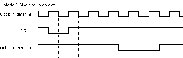
00(Mode 0)- Single Square Wave
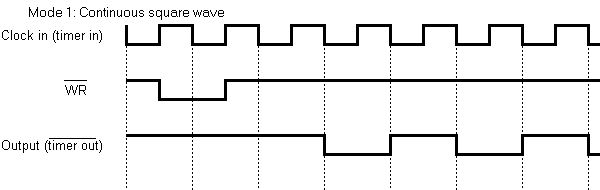
01(Mode 1)- Square Wave
10(Mode 2)- Single Pulse on TC(terminal count)
11(Mode 3)- Pulse every TC
Mode 0: In this mode, timer gives only one cycle of square wave, the output remains high for 1/2 count and remain s low for 1/2 count. If count is odd it remains high for (n+1)/2 and low for (n-1)/2. Where n is count value. Wave width depends on two factor: one is Input clock pulse frequency, and the other is count loaded in counter.
Mode 1: This mode is similar to single square wave in operation but the when counter becomes zero, the count value is automatically reloaded. Thus it provides continuous square wave.
Mode 2: This mode gives a single clock pulse as a output of the end of the count.The output is high normally, but it becomes low for 1 clock pulse and again it will become high and remain high.
Mode 3: This mode is similar to mode 2 but when the counter becomes zero the count value is automatically reloaded. Thus it provides continuous pulses.


Plz i want one example of 8155 timer plz sir
ReplyDeleteI want one example of it plz plz request sir
ReplyDelete