Showing posts with label 8155 PPI. Show all posts
8155 Timer
The 8155 timer consists of two 8-bit registers.
1. 8-bit LSB and 8-bit MSB.
2. In these 16 bits, 14 bits are used for counter and two bit for mode selection.
3. The counter is a 14 bit down counter. It can operate in 4 different modes of operation.
Timer MSB:
|
|||||||
M2
|
M1
|
T13
|
T12
|
T11
|
T10
|
T9
|
T8
|
Timer LSB:
|
|||||||
T7
|
T6
|
T5
|
T4
|
T3
|
T2
|
T1
|
T0
|
We can select mode using two bits M2 and M1.
M2 M1
00(Mode 0)- Single Square Wave
01(Mode 1)- Square Wave
10(Mode 2)- Single Pulse on TC(terminal count)
11(Mode 3)- Pulse every TC
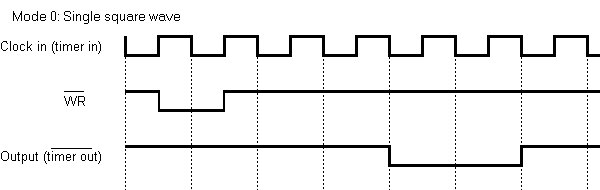
Mode 0: In this mode, timer gives only one cycle of square wave, the output remains high for 1/2 count and remain s low for 1/2 count. If count is odd it remains high for (n+1)/2 and low for (n-1)/2. Where n is count value. Wave width depends on two factor: one is Input clock pulse frequency, and the other is count loaded in counter.
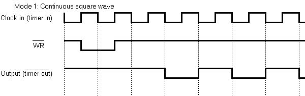
Mode 1: This mode is similar to single square wave in operation but the when counter becomes zero, the count value is automatically reloaded. Thus it provides continuous square wave.
Mode 2: This mode gives a single clock pulse as a output of the end of the count.The output is high normally, but it becomes low for 1 clock pulse and again it will become high and remain high.
Mode 3: This mode is similar to mode 2 but when the counter becomes zero the count value is automatically reloaded. Thus it provides continuous pulses.
Mode 0: In this mode, timer gives only one cycle of square wave, the output remains high for 1/2 count and remain s low for 1/2 count. If count is odd it remains high for (n+1)/2 and low for (n-1)/2. Where n is count value. Wave width depends on two factor: one is Input clock pulse frequency, and the other is count loaded in counter.
Mode 1: This mode is similar to single square wave in operation but the when counter becomes zero, the count value is automatically reloaded. Thus it provides continuous square wave.
Mode 2: This mode gives a single clock pulse as a output of the end of the count.The output is high normally, but it becomes low for 1 clock pulse and again it will become high and remain high.
Mode 3: This mode is similar to mode 2 but when the counter becomes zero the count value is automatically reloaded. Thus it provides continuous pulses.
Tag :
8155 PPI
8155 Control Register
D7
|
D6
|
D5
|
D4
|
D3
|
D2
|
D1
|
D0
|
Timer command
|
IEB
|
IEA
|
PC (ALT1 and ALT0)
|
PB
|
PA
|
||
Control register also called command register.
It is a 8-bit which defines different functions.
It defines the function of different ports such as input, output or handshaking mode.
It also defines timer command for timer to start and stop.
Timer command:
00 -No effect
01 -Stop counting if timer is running. No operation if counter is not running.
10 -Stop after terminal counter is reached.
11 -Start timer if timer is not running. If timer is running reload the TC and then continue.
Interrupt Enable for PA and PB(D4 and D5):
1- enable
0- disable
Input or output for PA and PB respectively:
1-output
0-input
Tag :
8155 PPI
8155 functional Block Diagram
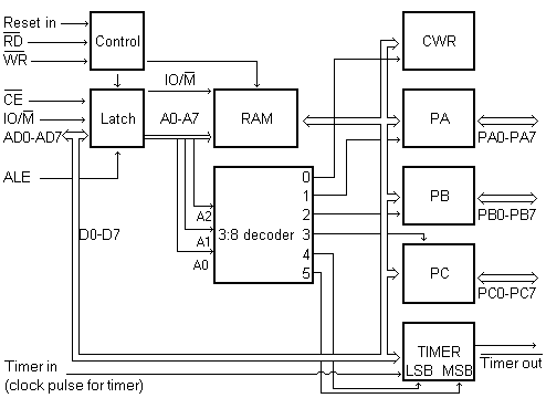
This section has 256x8 Memory. It means 256 location of 8 bit each.
When CE-bar=0, IO/M-bar=0 and ALE is activated the address in AD0-AD7 are latched and will be provided to 256 memory location.
| A2 | A1 | A0 | Port |
| 0 | 0 | 0 | Command/status reg. |
| 0 | 0 | 1 | PA |
| 0 | 1 | 0 | PB |
| 0 | 1 | 1 | PC |
| 1 | 0 | 0 | Timer LSB |
| 1 | 0 | 1 | Timer MSB |
Tag :
8155 PPI
